
De facto standard consolidated protocol
1979 Birth of a standard
In the turbulent world of 1979, as the Soviet invasion of Afghanistan took place and Iran’s Islamic revolution began, the company that developed the first PLC in 1968, Modicon, developed a communication protocol so that PLCs could communicate with add-on modules in industrial applications.
Thus in 1979 Modbus was born, a standard, open and universal protocol. Although a large number of protocols have followed, Modbus has the widest acceptance in industrial automation due to its simplicity, which allows a complete implementation with minimal code on any processor.

The specifications of this protocol are maintained and updated by modbus.org, a global association that ensures interoperability between different manufacturers. Companies such as Ibercomp, a member of this association, actively participate in its improvement and dissemination.
Full documentation on this protocol is available at: https://modbus.org/.
RS485 is the most common choice for implementing Modbus due to its ability to transmit data over long distances and connect multiple devices on a single network. It is a robust and reliable standard, capable of operating in industrial environments with high levels of electromagnetic noise.
As an anecdote, an installation for groundwater monitoring was made at Palma de Mallorca Airport, using abandoned telephone wires from the 70’s and cables passing through a 30000V tray of the runway beacon lamps. Despite the adverse conditions, the 15 km network operated for many years without problems.
On another occasion, one of our customers installed a system in a 180-room hotel with a chaotic structure and many splices. Using an oscilloscope and terminating resistors of different values to cancel the reflections, an unorthodox solution, which made the system work for more than 15 years.
RS485 Modbus wiring
Choosing the right cable
For modbus to work properly over RS485 it is a prerequisite that the data cables are twisted. A practical and economical option is to use flexible shielded Ethernet cable. Shielding protects against electromagnetic interference, ensuring a more stable signal and better integrity of the transmitted data.
Be twisted, as this reduces external interference and electromagnetic distortions generated by the cables themselves, since the magnetic fields created by the currents in opposite directions cancel each other out.
This is key to avoid communication problems in long RS485 networks or with many connected devices.
The fact that it is flexible prevents it from breaking; with rigid cables it is very easy for them to break and this failure to go unnoticed. An installation can work perfectly well with a rigid cable, but a not very careful technician or the vibrations will end up damaging the cable.
1.5mm2 unstranded power cable over long distances is likely to cause problems. At this point the material of the cables must also be taken into consideration, you cannot mix different metals such as copper and aluminum. If this is done with moisture there will be galvanic currents that will destroy the poorer metal.
If you can use KNX data cable, which is also stranded without problems, although in practice, thinner cable tends to offer better results. The reason is that thinner cable has less capacitance and less susceptibility to interference, which helps to minimize signal distortions.
Easy pair assignment using Ethernet cable
To take advantage of Ethernet cables in RS485 installations, we recommend the following layout:

Blue pair for data:
◦ Blue connected to line A.
◦ Blue-white connected to line B.
◦ (Easy to remember: “Blue” for “A” and “Bluewhite” for “B”).
Brown pair for GND.
Brown and white-brown connected to GND, ensuring that all devices are connected to the same ground potential.
Orange pair for food:
If the devices require 12V or 24V power supply and have low power consumption, the orange pair (orange and orange-white) can be used.
Green pair in reserve:
The green pair is left free as a reserve. It is recommended not to cut it and to leave it rolled up in the installation for future use.
Screen connection (mesh)
The shield of the cable should be connected to GND at only one end of the RS485 line, preferably at the end closest to the master device. It is important that no current flows through the shield, since its function is exclusively to act as a shield against interference.
It is also important to note that the Modbus network must be one line with one beginning and one end. No star configuration or branching of the network is allowed. Only patch cords or T-connections are accepted, with a maximum of 20 cm.
RS485 Network Limitations
Modern RS485 transceivers can support more than 128 devices connected on a single line. However, it is recommended to limit the number of devices to around 40 per line to avoid overloading the network. Here are some guidelines:
Network segmentation:
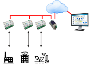
Dividing the installation into small panels with their own RS485 line improves stability and facilitates maintenance. With Ibercomp’s Ethernet-RS485 converters, you can access several RS485 lines in parallel, allowing centralized management.
Transceivers:
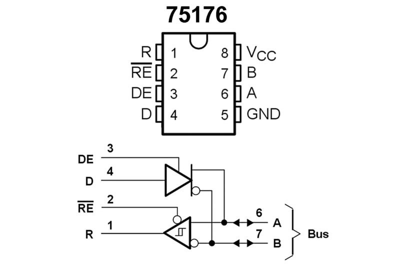
It is important to check the pinout of RS485 transceivers, such as the 75176, where line A is labeled positive (+) and line B is labeled negative (-). Some devices may have reverse labeling, so it is crucial to verify that positives are connected to positives and negatives to negatives to ensure proper communication.
LoRa to RS485 Converters for Remote Modbus Equipment Connection:
In some installations where Modbus equipment is located at a considerable distance and RS485 cabling is not practical, an effective solution is the use of LoRa to RS485 converters. LoRa (Long Range) is a wireless communication technology that allows data transmission over long distances with low power consumption.
A clear example could be an ambient light sensor on a rooftop that is isolated, it is not practical to run a cable up ten floors. It can also be the case of a swimming pool panel that is distant from the building and there is no way to run the cable. 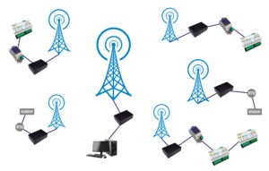
LoRa has some limitations:
It is important to note that the data transmission speed using LoRa is relatively slow, typically around 1200 baud. While this speed may not be suitable for applications requiring high real-time data exchange, it is sufficient for many monitoring and control applications where data is updated less frequently.
A radio solution is always susceptible to interference and packet loss. The network layer of LoRa equipment tries to solve this problem, but since it uses free frequencies such as 433MHz, anyone can step on the frequency. LoRa also limits the occupancy windows, so it is not convenient to make a continuous reading.
RS485 robustness
The most robust devices include a three-level protection that ensures greater durability and resistance to adverse conditions common in industrial installations. This protection includes:
◦ TBU (Transient Blocking Unit): Protects against overcurrents, cutting off the current flow when a predetermined threshold is exceeded.
TVS (Transient Voltage Suppressor): Acts against surges, absorbing transient voltage spikes such as those generated by electrostatic discharge (ESD) or lightning.
Gas Discharger: Protects against extreme overvoltages caused by atmospheric discharges or high energy peaks, shunting the dangerous current to ground.
These three levels of protection work together to protect transceivers and other sensitive components of RS485 devices by providing resistance to overvoltage, overcurrent and electrostatic discharge.
Our industrial equipment includes these protections, and in new designs we integrate them, but if you use equipment that does not have line protections, it is advisable to add them.
It is not uncommon for equipment that does not have protection against storms or sudden power surges to be damaged.
Troubleshooting RS485 Installations
To install and maintain an RS485 installation it is necessary to acquire skills, it must be taken into account that if a transceiver is damaged, there is a short circuit or a cable breaks, the whole line stops communicating. Sometimes breakdowns or failures are very strange, as in the case of an installation of a customer in a hotel with 330 rooms, which worked correctly but at times 40 rooms stopped communicating. Checking the rooms one by one they were working correctly, but when we checked them frame by frame we discovered that the electrician had mistakenly connected the data output of a PIR NPN sensor to one of the bus data lines. When someone entered the bathroom in that room, the entire line stopped working. The room was unoccupied and used as a storage room, so the bathroom was present from pears to grapes.
When an RS485 network has communication failures, it is important to have the right tools to diagnose the problem efficiently. The following are some methods and recommendations for identifying and resolving network problems.
Using the oscilloscope to verify the line
Portable oscilloscopes are ideal tools for checking whether the data signal on the A and B lines is correct. These devices can be purchased for less than €50 from online retailers, and any of them will be useful for this task.
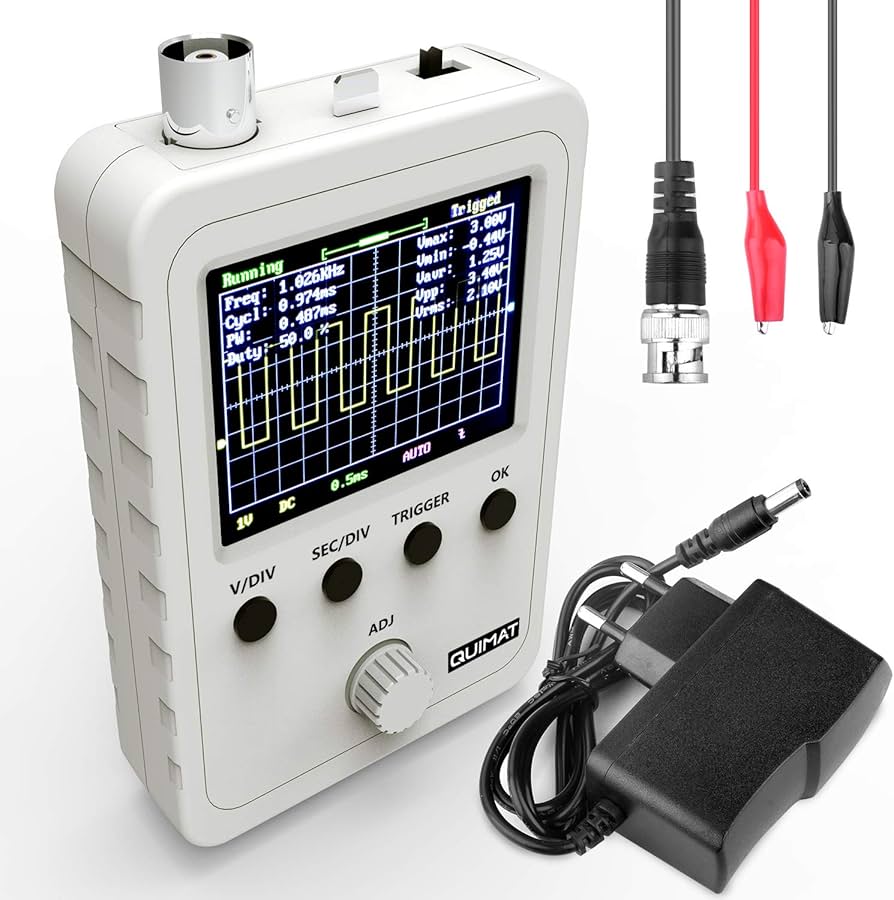
In order to check the status of a line, connect the oscilloscope clamp to GND and check the signals on the A and B lines. The signals should appear as square waves transiting between approximately 0V and 3.3V.
If the transition is not clean and a fainter delayed signal is seen, there is a reflection and a terminating resistor is needed at one end. We recommend playing with resistors of different values, starting with 1K, 470Ohms, 270Ohms, 180Ohms up to 120Ohms. The larger the resistor the less the main signal will be attenuated.
If the signals are attenuated, this could indicate a short in a transceiver or cable. In this case, it is advisable to check the transceivers one by one, as this may be the cause of the failure.
Alternatives without oscilloscope
If you do not have an oscilloscope, you can use a true RMS tester or even an alternating mode tester to measure the signal level. Although less accurate, these instruments can help verify if the signal level is low, which may indicate communication problems.
Here we can connect the tester in alternating mode to lines A and B to check that a signal is observed, even if it is low. This can give an indication of whether the signal is present or if there is a significant problem in the network. A normal voltage is usually above 3V when there is more or less continuous data transmission.
Another alternative, when there is a shortage of means, is to use a pouch battery and a bulb in series. From the positive goes to the bulb, and from the bulb to the A signal. Signal B is connected to the negative, that is to say to B. For this test it is better if no data is being transmitted. On the other side of the line there should be 4.5V and the bulb should always be off. If it is on, there is a short circuit and if there is no 4.5V, there is a short circuit. 
Method for identifying faults in large installations
Using the binary search technique, in large installations, such as a hotel room corridor, it is not always the most appropriate to disturb 40 customers by opening frames to perform a check. It is best to split the line to identify the point of failure, following a series of steps:
◦ Open the line on the first device.: Start by disconnecting the line on the first device in the series. Make sure that the first device communicates correctly. If it does, proceed to the next step.
◦ Split the line in half: If the first device communicates well but the fault persists, split the line into two halves. Check if the first half is working correctly.

Binary logarithm: Continuing with this approach, each time half of the line works, continue dividing the rest. In log 2 (n) times, you will be able to isolate the problem. This method is efficient, especially in large networks.
Common problems and how to solve them
◦ Signal attenuated with distanceIt is normal for the signal to weaken with distance on long lines. If some equipment communicates intermittently or stops communicating, it may be due to attenuation. Check to see if the network extends too far without signal boosts or if the transceivers are overloaded. Consider the use of repeaters or signal boosters if the distance is considerable.
◦ Cut in the data cables.If the communication works well up to a certain point and then there is no signal, it is possible that one of the data cables is cut. Check the integrity of the cables to make sure there are no discontinuities. Use tools such as a cable tester to identify possible short circuits or continuity faults.
◦ Equipment with damaged transceivers: A damaged transceiver may draw more current than the power system can provide, which could cause the power supply to cut out or overload. If a piece of equipment is failing, check if its transceiver is in good condition and replace it if necessary. Make sure that the power supply is capable of supporting the power consumption of all connected devices.
With a little ingenuity and patience, most problems in an RS485 network can be solved without major complications. In addition, in Ibercomp equipment, whenever possible, the transceivers are mounted in sockets for quick and easy replacement in case of failure. Other manufacturers solder the transceivers. It is also possible that the protections may be damaged and appear to be short-circuited.
Modbus Network Management Software.
Most of today’s SCADA and HMI systems include libraries that natively support the Modbus protocol, which facilitates integration and communication with devices. If you work with open software platforms, such as NodeRED, you don’t need to worry too much about managing the Modbus protocol either, as they usually have pre-built modules that take care of that task.
At Ibercomp, we also provide our own fully tested libraries in JAVA, designed to ensure a robust and efficient implementation of Modbus in various environments. However, we have identified a common mistake in some of our customers who develop software for Modbus networks: they create monolithic applications where, for each cycle, a Modbus register is accessed, a decision is made, the graphical interface is updated, and so on. This tends to slow down application performance.
For testing our equipment we offer the open source application modbusTest, and you can also find valid test programs on modbus.org.
The optimal solution is to structure the software in layers and use multithreaded applications. Each thread should be responsible for managing the reading of a Modbus gateway, constantly copying data to memory (either via arrays, an MQTT server or a RAM database such as MariaDB). In this way, decisions and updates to the graphical interface are made directly from memory, while changes to the system are updated by triggers that send commands to the Modbus devices.

It is important to avoid active waits, as they only consume processor resources without improving efficiency. If a Modbus control application consumes 100% of CPU capacity, it is probably poorly designed. High CPU usage generates heat, which can increase the likelihood of system failures.
We have developed applications capable of managing up to 70,000 Modbus variables with a CPU consumption of only 6% and refresh times of less than 2 seconds. Although it is possible to further improve response times, achieving more than 10 updates per second becomes unrealistic when a large number of devices are connected.